Blog & News
Hydraulic Shock Absorbers for Industrial Electrical Applications
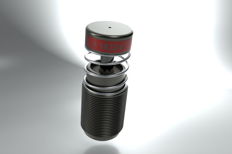
How a Hydraulic Damper Works
The operating principle of these devices is based on the forced passage of oil through calibrated internal orifices. When the rod is stressed by impact, the fluid is pushed through these controlled-section passages, generating a resistance proportional to the input speed.
Energy is thus progressively absorbed along the stroke, avoiding the force peak and the resulting rebound that would occur with a rigid stop.
This damping mechanism is combined with a return spring which, at the end of the absorption phase, returns the rod to its resting position. Internally, a one-way valve manages the oil flow in both directions, ensuring that the reset phase occurs rapidly — in fractions of a second — without interfering with the active damping phase.
This fast cycle is particularly critical in automatic reclosing applications of network circuit breakers, where the device must be ready for a new operation within a very short time after the previous one.
Types of Hydraulic Shock Absorbers: three solutions for as many application needs
There is no universal shock absorber for the industrial electrical sector. The application specifications — rated voltage of the switchgear, type of contact movement, available space, frequency of operations — determine which configuration to adopt.
The available solutions are three, each designed for a well-defined technical context.
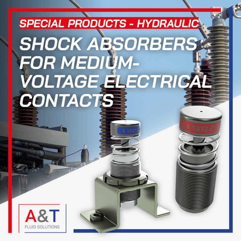
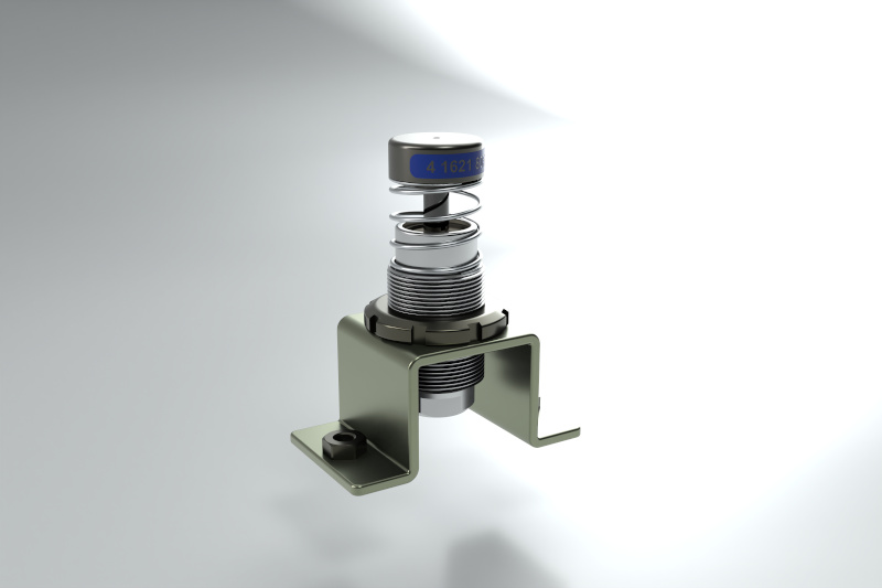
Shock absorbers for medium voltage switchgear
Designed to be directly integrated into medium voltage electrical switchgear, these devices stand out for their extremely compact dimensions combined with high performance. Compactness is not a compromise, but a technical specification: the internal spaces of MV switchgear impose precise dimensional constraints, and the device must ensure its effectiveness without interfering with other components of the equipment.
Among these solutions are also shock absorbers for medium voltage switchgear designed for integration into interruption systems.
High-performance shock absorbers for the high voltage sector
Dedicated to high voltage circuit breakers, these dampers are specifically designed to prevent pole rebound — a phenomenon that, at high voltage levels, can have serious consequences on dielectric strength and the integrity of the arc extinction system. In this context, the repeatability of the damping curve and the stability of performance over time are critical parameters.
In high voltage applications, high-performance solutions are available, designed to ensure the stability of the damping curve over time.
Self-compensating progressive shock absorbers
This series is designed for the damping of fast-moving elements subject to high loads. The distinctive feature is the progressive response: resistance increases as a function of impact speed, adapting the braking profile to the actual conditions of each cycle.
Self-compensation allows the device to maintain constant performance as operating conditions vary, without the need for manual adjustment.
In the presence of variable loads, self-compensating progressive shock absorbers can be used, capable of adapting the response to operating conditions.
Technical advantages and impact on system reliability
Integrating a properly sized energy dissipation system into the architecture of an electrical switchgear does not only mean protecting mechanical parts from impact wear. It means acting on multiple levels of the system reliability chain.
The main advantages can be summarized as follows.
- Elimination of mechanical rebound: in disconnectors and circuit breakers, even a rebound of a few millimeters of the contacts can cause unwanted secondary electric arcs, with potentially destructive effects on the contact surfaces.
- Reduction of structural stress: controlled stopping reduces impulsive forces transmitted to the switchgear frame, extending the operational life of support components and bolted connections.
- Support for rapid reclosing cycles: the automatic and fast reset of the damper ensures that the device is operational for the next operation without downtime, a crucial aspect for circuit breakers subject to automatic reclosing cycles imposed by network protection.
- Operation over extended temperature ranges: design for an operating range between -20°C and +70°C ensures device effectiveness even in the most critical environmental conditions, such as outdoor substations or industrial environments with strong seasonal temperature variations.
- Reduced maintenance: the combination of a high guaranteed number of cycles and long operational life directly translates into a reduction in scheduled maintenance interventions, with tangible benefits on the total cost of ownership of the equipment.
Motion management: axial and rotary
An often underestimated aspect during the design phase concerns the compatibility between the type of motion of the operating mechanism and the installation mode of the damper.
In systems with linear motion — the most common configuration in MV switchgear contacts — the device is mounted coaxially with the direction of motion, so as to receive the impact force along the rod axis. This geometry optimizes damping efficiency and eliminates radial forces on the shaft.
In mechanisms with rotary actuation, on the other hand, it is necessary to introduce a system of linkages to convert rotary motion into linear motion before it reaches the damper.
This is not a marginal detail: directly applying rotary motion to a rod not designed to receive significant radial forces can compromise seal integrity and drastically reduce component life. The correct design of the linkage is therefore an integral part of the solution, not a separate element.
Applications: where Hydraulic Shock Absorbers make the difference
The application field of these dampers is defined by the technical context for which they are designed. Engineers and designers typically encounter them in the following areas:
- Medium voltage switchgear (MV switchgear): both in fixed and withdrawable configurations, where the contacts of earthing switches, vacuum circuit breakers and disconnectors require end-of-stroke impact control.
- High voltage circuit breakers (HV circuit breakers): particularly in SF6 or vacuum configurations, where pole opening speed is high and contact rebound must be positively excluded.
- Mechanical operating systems of switchgear: spring, motor or lever mechanisms that control the opening and closing of main circuits, subject to high end-of-stroke impact speeds.
In all these cases, the function of the damper is not isolated: the device operates in synergy with the other components of the operating system (charging springs, linkages, mechanical end stops) and must be sized considering the entire dynamic profile of the operation, not only the impact speed.
How to choose the correct Hydraulic Damper
The selection of a hydraulic damper for industrial electrical applications cannot be approximate. The parameters to be defined during the specification phase are precise and their correct evaluation is a necessary condition to achieve the expected performance.
Among the main criteria to consider:
- Kinetic energy to be dissipated per cycle: expressed in joules, it is the fundamental parameter that determines the capacity of the shock absorber. It is calculated from the mass of the moving parts and their impact speed.
- Impact speed: directly influences the force profile generated by the damper. High speeds require devices with progressive characteristics to avoid excessive force peaks.
- Frequency of operations and total operating cycles: a system subject to numerous daily operations — such as a network circuit breaker in an area with frequent disturbances — requires a device certified for a high number of cycles, with well-documented wear characteristics.
- Environmental installation conditions: minimum and maximum operating temperature, presence of humidity or condensation, exposure to dust or chemical agents. The certified operating range of the device must cover the entire spectrum of real conditions.
- Type of motion and installation geometry: axial or rotary movement, available space, mounting method. For switchgear with particularly limited space, dimensional compactness becomes a full-fledged technical requirement.
- Reset requirements: in rapid reclosing systems, the return time to the resting position is a parameter to be verified against the circuit breaker cycle times.
When these parameters are precisely defined, the selection of the most suitable device — among medium voltage, high voltage or self-compensating progressive solutions — becomes a structured engineering operation, not an approximation by analogy.