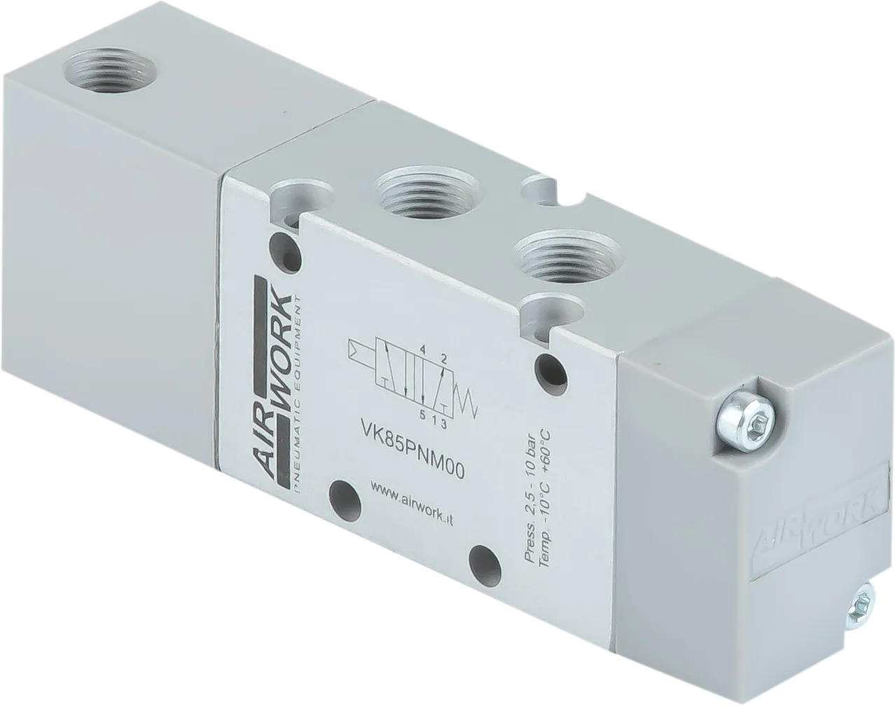
Pneumatic Actuated ValvesVK Series
- Guaranteed to function for 50 million cycles
- CNC machined body, anodized and painted to ensure precision and durability over time
- Internal metal components to limit thermal expansion
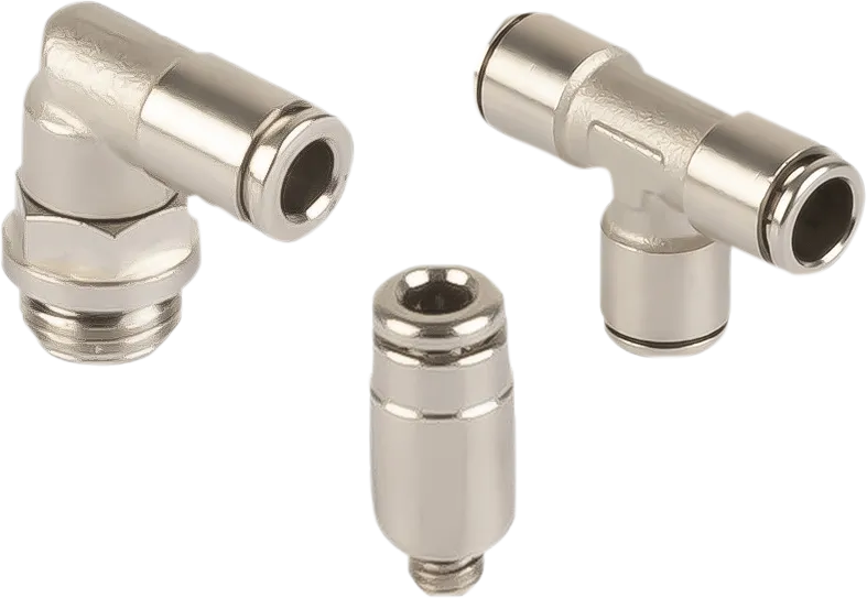
Airwork’s pneumatic valves combine big resistance, reliability and versatility of assemblage; the VK series can be assembled in several ways: in-line, on panel, on multiple bases, on manifolds and on cylinders.
Available size are 1/8,1/4 and 1/2, the available functions are 3/2, 5/2 and 5/3.
What Pneumatic Valves Are and What They Are Used For
Pneumatic valves represent the beating heart of every pneumatic automation system, acting as control elements that precisely manage the flow, direction, and pressure of compressed air within industrial circuits.
These devices make it possible to convert pneumatic energy into controlled movements of actuators, ensuring operational efficiency and reliability in even the most complex production processes.
In the context of modern automation, pneumatically actuated valves stand out for their ability to operate in particularly harsh environments, where operating conditions require robust and reliable components.
The VK Series perfectly embodies this design philosophy, offering advanced technical solutions for industrial applications that demand high performance standards.
How a Pneumatic Valve Works
The operation of a pneumatic valve is based on a principle that is elegant in its simplicity: an internal moving element, known as a spool or poppet, moves within the valve body to open, close, or divert the path of compressed air.
This movement is activated by a pneumatic signal acting on a control piston, generating the force required to overcome the resistance of the sealing elements and allow the valve to switch.
In pneumatically actuated valves, the control energy comes from an external pneumatic signal which, applied to the surface of the internal actuator, creates a pressure differential.
When this pressure exceeds the opposing force of the return spring or the opposite signal, the spool moves rapidly into the required configuration.
The sealing system ensures that the different pressure chambers remain isolated, guaranteeing flow directionality and the energy efficiency of the circuit.
A crucial aspect concerns the switching speed: modern pneumatic valves are designed to complete opening and closing cycles within a few milliseconds, enabling precise control of high-frequency processes.
This fast response, combined with the ability to operate without a minimum pressure differential, makes pneumatically actuated valves particularly versatile across a wide range of industrial applications.
Types of Pneumatic Valves
The classification of pneumatic valves is based on two fundamental parameters: the number of ports and the number of positions.
Ports represent the physical connections of the valve (supply, outputs to actuators, and exhausts), while positions indicate the stable configurations that the valve can assume during operation.
The most common configurations in industry include:
- 3/2 valves: featuring three ports and two positions, they are ideal for controlling single-acting cylinders. In the rest position they can be normally closed (NC) or normally open (NO), allowing the cylinder to remain retracted or extended respectively when no control signal is present
- 5/2 valves: with five ports and two positions, they represent the standard solution for actuating double-acting cylinders. They ensure simultaneous control of the supply and exhaust of both cylinder chambers
- 5/3 valves: add a third intermediate position that can be configured with different functions, such as exhausting both outputs or blocking the ports to hold the cylinder in position
From the standpoint of operational stability, a distinction is made between monostable and bistable valves.
The former, equipped with a return spring, require only a single control signal and automatically return to their rest position when the signal ceases.
The latter require two distinct signals to switch between positions and maintain the last assumed configuration even in the absence of a signal, making them ideal for applications that require position holding without continuous air consumption.
How to Read a Pneumatic Valve: ISO Standard Symbols
Correct interpretation of pneumatic symbols is a fundamental skill for designers and maintenance technicians. The ISO 1219 standard defines a universal system for the graphical representation of valves, allowing unambiguous interpretation of pneumatic diagrams regardless of language or country of origin.
A valve symbol is made up of adjacent rectangles, each representing a functional position. Inside each rectangle, solid lines indicate open air paths, while perpendicular segments indicate closed ports.
Arrows show the direction of flow when present. Outside the rectangles, numbers identify the physical connections according to the CETOP convention:
- 1 for supply,
- 2 and 4 for outputs to actuators,
- 3 and 5 for exhausts.
Actuations are represented by symbols placed at the ends of the rectangles: a triangle indicates pneumatic actuation, a rectangle with a diagonal line indicates electrical actuation, and a semicircle indicates manual actuation. The presence of a spring, represented by a zigzag line, identifies the automatic return device in monostable valves.
For a 5/2 bistable pneumatically actuated valve, the symbol will show two rectangles with the internal flow configurations, two triangles at the ends indicating pneumatic controls, and the absence of springs, highlighting the need for two distinct signals to switch.
The reference position for identifying the connections is always the right-hand rectangle, corresponding to the rest state or the last position assumed.
The Technical Advantages of Pneumatic Actuation
Pneumatic actuation offers numerous technical advantages over other control solutions. The high switching force, generated directly by compressed air pressure, makes it possible to actuate large valves with low energy consumption. As there are no active electrical components on the main valve, the risk of overheating is eliminated and compatibility with ATEX environments or explosive atmospheres is ensured.
Modularity is another key strength: pneumatic valves can be easily integrated into valve manifolds, reducing overall footprint and simplifying pneumatic piping. Modular systems also allow fast maintenance operations, with individual components replaced without dismantling the entire manifold.
From an operational speed perspective, pneumatically actuated valves ensure extremely short switching times, on the order of a few milliseconds, which are essential for pick-and-place applications, high-speed packaging, and automated machinery where productivity directly depends on cycle speed.
The ability to operate with zero differential pressure also makes them particularly suitable for vacuum or low-pressure applications.
Selection Criteria and Industrial Applications
Choosing the appropriate pneumatic valve requires careful analysis of the system’s operating parameters. The nominal flow rate, expressed by the flow coefficient (Cv or Kv), must be sized according to the cross-section of the cylinder to be controlled and the required actuation speed.
Insufficient flow capacity results in slower operating cycles and efficiency losses, while unnecessary oversizing leads to higher costs without performance benefits.
The operating pressure is another critical parameter: it is necessary to verify that the available supply pressure falls within the operating range of the valve, typically between 2 and 10 bar for standard industrial applications.
Lower pressures may compromise switching reliability, while excessive pressures reduce the service life of the seals.
Environmental conditions significantly influence the choice of construction materials. In aggressive environments or in the food industry, stainless steel bodies or certified technopolymers are preferred, while for standard applications anodized aluminum offers an excellent balance between strength and lightness.
The operating temperature must remain within the specified limits to ensure the integrity of seals made of NBR, FKM, or EPDM, depending on requirements.
In the automatic assembly sector, pneumatic valves control grippers, positioning systems, and clamping devices with cycles reaching thousands of switchings per hour.
In the packaging industry, they manage the opening and closing of jaws, the ejection of defective products, and movement on conveyor belts.
In the material handling sector, they actuate locking systems, flow diverters, and lifting platforms, ensuring safety and repeatability of operations.
The VK Series Pneumatic Valves represent a complete technical solution for the needs of modern industrial automation, combining robust construction, mounting versatility, and reliable performance under all operating conditions.
Maintenance and Performance Optimization
Proper maintenance of pneumatic valves significantly extends their service life and maintains high system performance.
Compressed air treatment plays a fundamental role: the presence of particulate matter, condensate, or oily contaminants accelerates seal wear and can cause malfunctions.
It is essential to ensure that the air is filtered to at least ISO 8573-1 purity class 7-4-4, with filters installed upstream of the distribution circuit.
Lubrication requires special attention. Some modern valves are designed to operate without lubrication, thanks to the use of self-lubricating materials in the seals.
For valves that require lubrication, it is crucial to use properly sized oil mist lubricators positioned as close as possible to the actuators, ensuring uniform distribution of lubricant within the internal chambers.
Periodic inspections should include checking for air leaks, easily detected using soapy solutions or ultrasonic detectors, as well as inspecting the condition of fittings and tubing. Even minor leaks, seemingly negligible, can add up to significant energy waste over the course of a year.
Cleaning exhaust ports and silencers prevents the buildup of impurities that could generate unwanted back pressure.
Predictive diagnostics, through monitoring switching times and air consumption, makes it possible to identify performance degradation situations at an early stage, planning maintenance interventions before unexpected machine downtime occurs.
This proactive approach integrates perfectly with modern Industry 4.0 systems, where intelligent sensors continuously communicate the health status of pneumatic components.